Hello, I’m very very new to InstaMAT. I’m trying to use the new terrain generator, and I am attempting to create a canyon. The default example shows how to do this with the Bezier Curve Node. After figuring out how to use the curve editor, I noticed that each point can have a specific width and color in the UI. I tried changing these values and it had no effect, since the global values overrode the individual point values.
My intent here is to create a canyon that has sloped start and end, where I can change the width of the canyon as I see fit along it’s route. In InstaMAT terms, I would simply create a grey scale foreground Bezier curve that is the canyon (like it is now in the tutorial example), but instead of the curve being uniform in brightness and width, it would vary in brightness and width based on the individual point settings.
Perhaps somehow this data is exported and some other node(s) makes use of these individual settings to recreate the image I’m trying to make. But I haven’t been successful yet with that. So it is likely my ignorance in how to use this node and create the result I’m looking for. If you look at the Paintbrush “Hard Round Pressure Flow” icon image, hopefully that will give you an idea of what I’m trying to do.
If I understand you correctly, something like this is what you’d need?
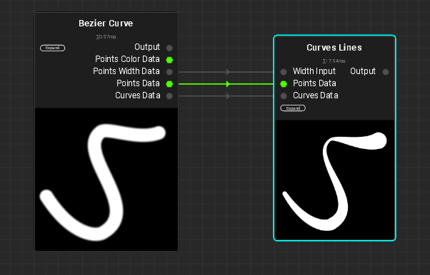
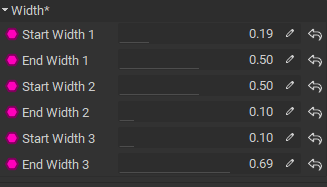
You can achieve this by adjusting the Start and End Width of every point in your curve in the “Bezier Curve” node:
You also need to flip the “Curves Output” bool to true. After that, you can input your “Points Width Data”, “Points Data” and “Curves Data” into the “Curves Lines” node and adjust the curve to your liking.
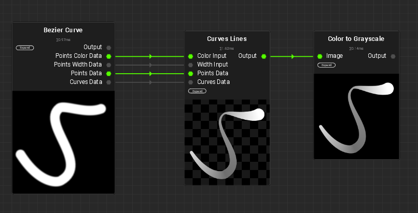
To get different grayscale values working, it’s best to set the “Curves Lines” node to color and use the color input together with the “Points Color Data” of the Bezier Curve node. In the Bezier Curve Node you can set Start and End color values for your points and feed them into the “Curves Lines” node. You can then convert the results with a “Color to Grayscale” node to grayscale.
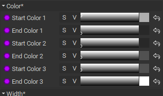
Color settings on the Bezier Curve node:
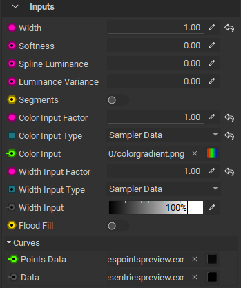
Settings on the Curves Lines Node:
Alternativley, you can use the “Spline Luminance” and “Luminance Variance” parameters on the “Curves Lines” node.
This is 100% what I need! Thank you very much! I didn’t know by changing the input width factor would expose the variable with input, and the same for the color. That is why I couldn’t find it. I greatly appreciate your help with this. I had just posted saying my version didn’t have those inputs, which is why I couldn’t find it. Now I understand. Thank you very much for your explanation!
I think your installation should be fine, the Curves Lines Node wasn’t available in the previous release and is a new node, so it looks like you are set up correctly.
Can you try to bump the “Width” and “Width Input Factor” on your Curves Lines node to 1.00?
Edit: Just see you changed your post and managed to fix it. Great, happy I was able to help!