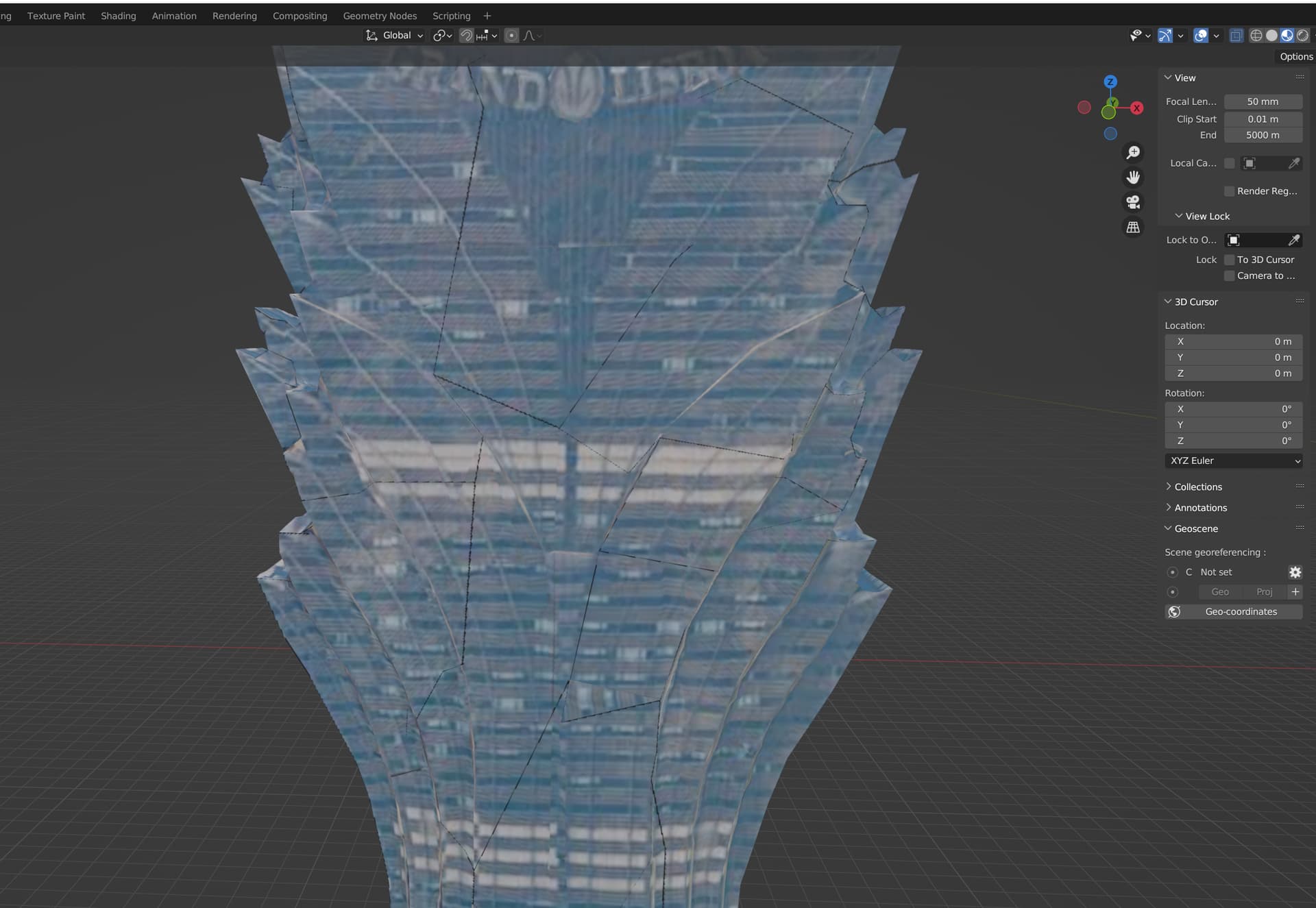
I have tried so far all options and combinations to avoid transparent edges, but whatever approach I choose, the objects I remesh are transparent along their edges.
The mesh I am processing is raw data / photogrammetry based and I followed this
and experimented with the different settings without any success.
I could get rid of the alpha channel on the UV, but this is not really a solution for the problem.
The solution should be very simple. I just need the UV shells to be strechted a few pixels, but the stretch importance does not seem to have any affect.
I helped myself out for the time beeing, with a Blender python script I created to work around this issue.
Maybe someone else finds this useful.
import bpy
import bmesh
from mathutils import Vector

# Set the desired pixel decrease
pixel_decrease = -1 / bpy.context.scene.render.resolution_x  # Normalize to UV space

# Get the active object and its mesh
obj = bpy.context.active_object
mesh = obj.data

# Check if the object has UV maps
if not obj.data.uv_layers:
    print("Error: Selected object has no UV maps.")
else:
    # Get the active UV map
    uv_map = obj.data.uv_layers.active

    # Use BMesh to work with mesh data
    bm = bmesh.new()
    bm.from_mesh(mesh)
    uv_layer = bm.loops.layers.uv.active

    # Function to find UV islands
    def get_uv_islands(bm, uv_layer):
        uvs = {}
        for face in bm.faces:
            for loop in face.loops:
                uv = loop[uv_layer].uv
                vert = loop.vert
                if vert not in uvs:
                    uvs[vert] = []
                uvs[vert].append(uv)

        visited = set()
        islands = []

        def bfs(vert):
            queue = [vert]
            island = set()
            while queue:
                v = queue.pop(0)
                if v not in visited:
                    visited.add(v)
                    island.add(v)
                    for edge in v.link_edges:
                        other_vert = edge.other_vert(v)
                        if other_vert not in visited:
                            queue.append(other_vert)
            return island

        for vert in uvs:
            if vert not in visited:
                island = bfs(vert)
                if island:
                    islands.append(island)

        uv_islands = []
        for island in islands:
            uv_coords = []
            for vert in island:
                uv_coords.extend(uvs[vert])
            uv_islands.append(uv_coords)

        return uv_islands

    # Find UV islands
    uv_islands = get_uv_islands(bm, uv_layer)

    # Decrease UV coordinates of each UV island by pixel_decrease
    for uv_coords in uv_islands:
        # Calculate the centroid of the UV island
        centroid = Vector((0.0, 0.0))
        for uv in uv_coords:
            centroid += uv
        centroid /= len(uv_coords)

        # Scale UV coordinates towards the centroid
        for uv in uv_coords:
            direction = uv - centroid
            uv += direction.normalized() * pixel_decrease

    # Update the mesh with the new UV coordinates
    bm.to_mesh(mesh)
    bm.free()

    # Ensure changes are updated
    mesh.update()
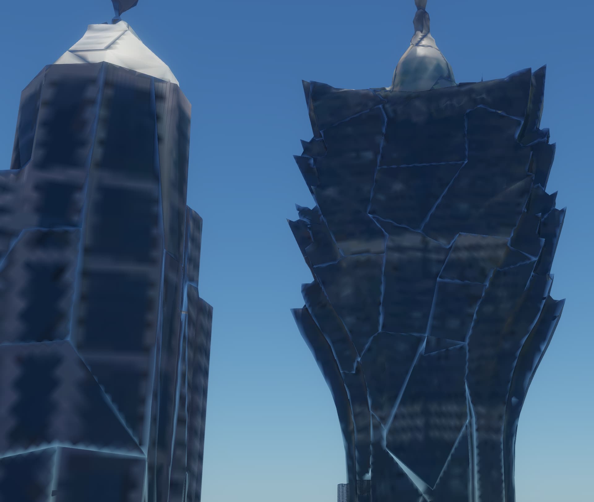
It’s not perfect, but it closes most of the gaps.
-1 pixel works best, without affecting the mesh too much
If someone has a proper solution or another idea I could try inside InstaLOD, that would be much appreciated!
Thank you for your post and for providing the python script. I’m glad you were able to arrive at a solution.
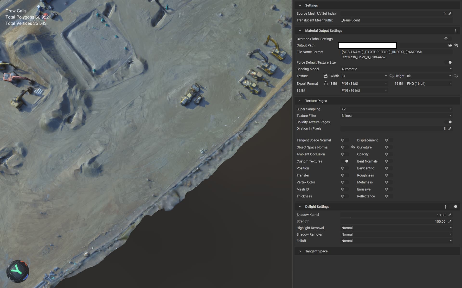
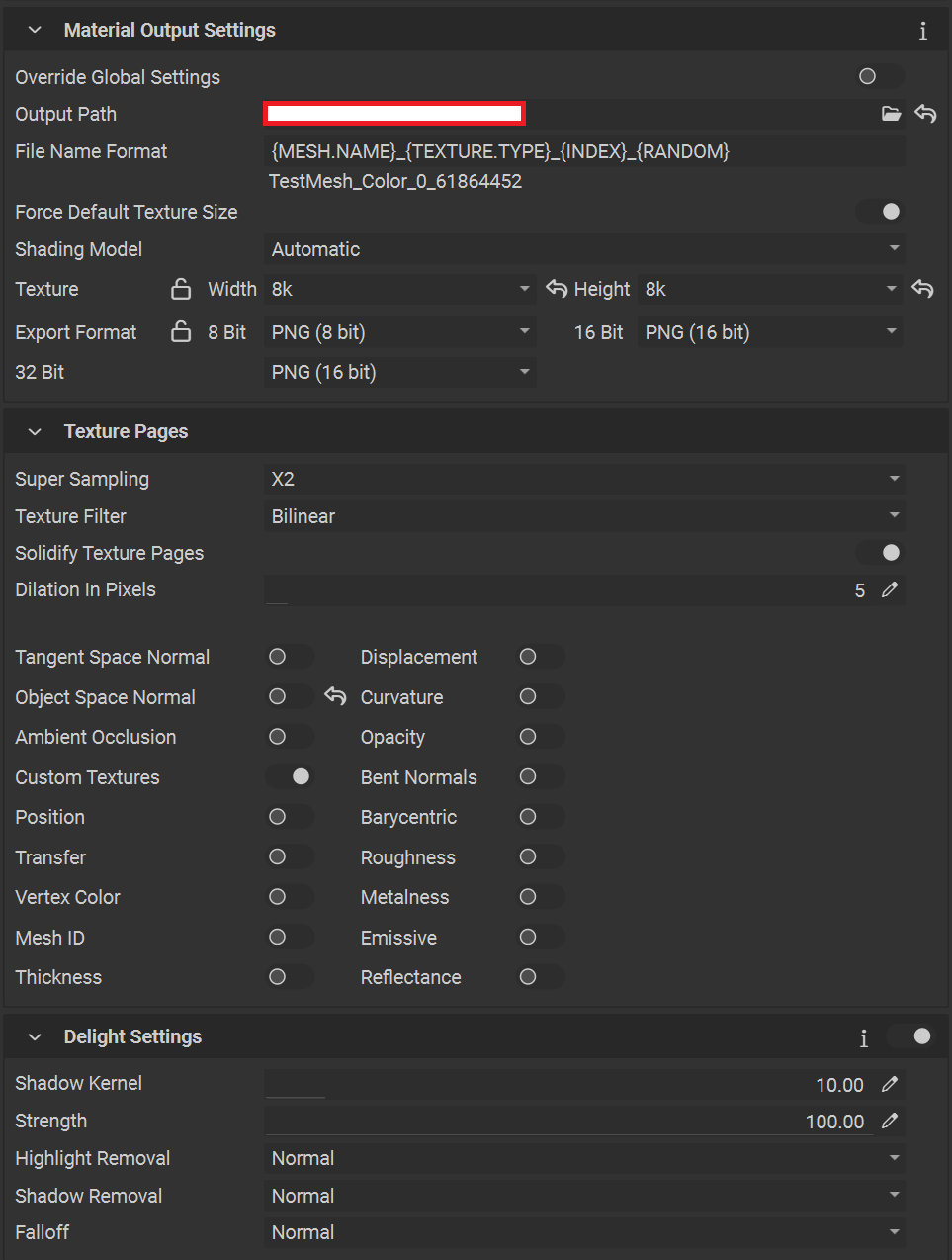
The first suggestion would be to increase the Gutter Size in Pixels setting. If you have already tried this, could you please provide some screenshots and a mesh file for us to test internally? If you do not wish to share this publicly, I can initiate a PM so that you can send the data privately.
I did experiment a little more and this is a common problem for me. It is not unique to the initial mesh/object.
Regardless which object type I import and then postprocess inside InstaLOD - as soon I do the export, the textures/mesh gets messed up. I can reproduce this with any material. I have tried .fbx, .glb/.gltf so far as import and export methods.
I noticed you attached the processed mesh but not the original. Would you be able to provide the original mesh so that we can test it internally? If you do not wish to share it publically, I can send a PM.
thanks for getting back!
Well actually (as I already explained) I can use any material and are able to reproduce the problem. Simply grab something from sketchfab.
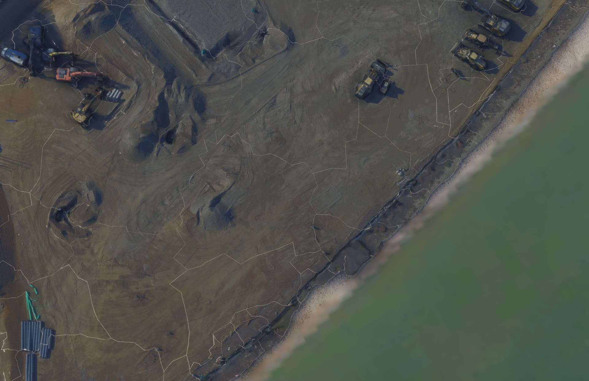
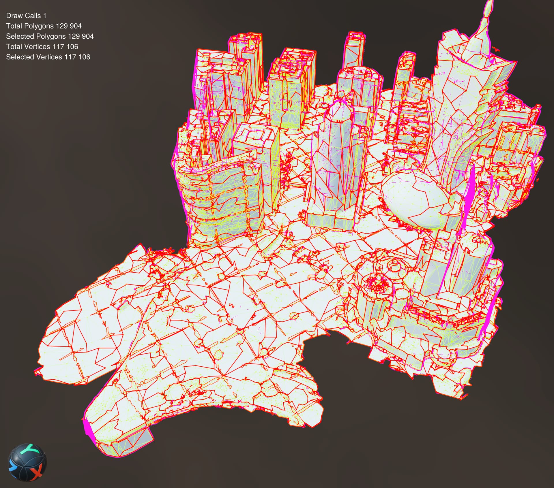
The construction site above is from there for example.
Once the remeshing is completed and I do the export into Blender, I get those transparent edges…
I have tested your profile on a scan from Sketchfab and was unable to reproduce the results you mentioned. The mesh did not have transparent gaps along the UV seams when importing it into Blender.
Also, the example result you have provided doesn’t seem to contain textures so I was unable to view the artifacts in Blender.
One thing I did notice is that your example result had many patches of areas where the vertices were not welded.
Before remeshing, could you try selecting the mesh and welding the vertices by going to Mesh > Vertex Welding from the main menu and choosing a small value such as 0.001 as the Welding Threshold?
In many cases it is also helpful to recalculate the normals of the mesh as well by going to Mesh > Recalculate Normals.
If you would be willing to share the link to construction site mesh from sketchfab I’d like to test it on that directly. Once I’m able to reproduce your results I will have a better understanding on how I can help.
I have remeshed countless objects in InstaLOD and have not seen this issue occur. It would be great to be able to narrow down the criteria for this behavior so that we can better understand the cause.
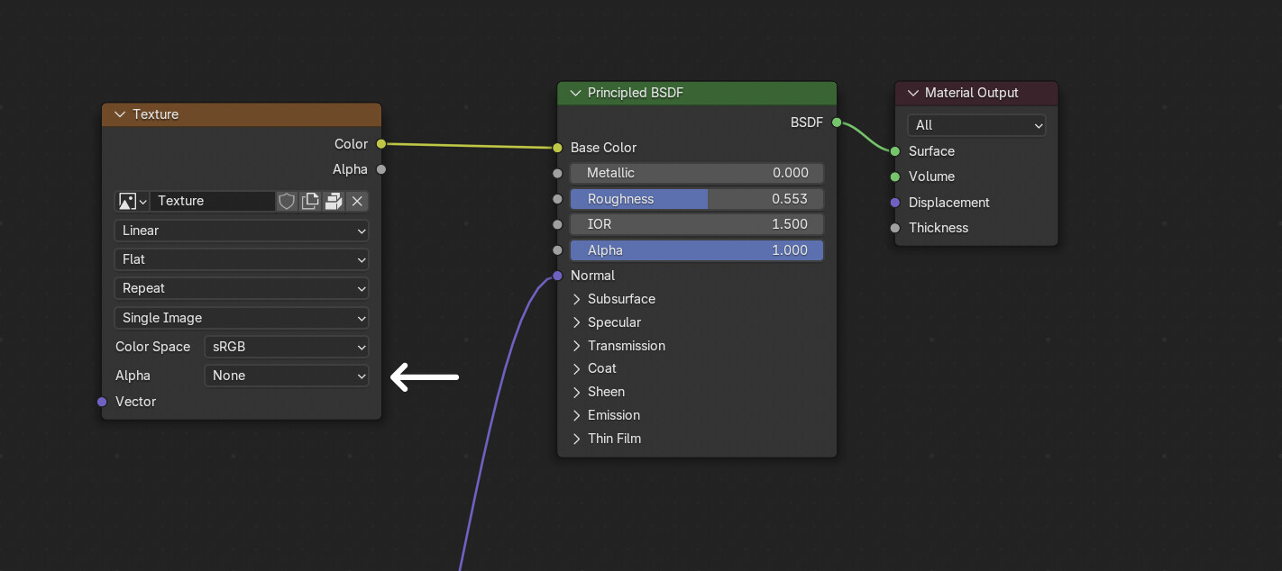
Another user on our Discord server mentioned having a similar issue. We’ve discovered that it appears to be related to how Blender is importing the textures of the remeshed asset. You can remove the lines along the UV shells by removing the texture it automatically supplies as the Alpha map to the Principled BSDF shader and setting the Base Color texture’s Alpha setting to None.