Starting out with Canvas: Beginners questions Thread

So, I´ll just use this thread to collect a few questions that arise for people like me, that are just starting out with Canvas, just like I did with the painting and material modes…

I should probably have followed a basic tutorial first, but I´ve done some shader work in Unreal and in other dccs and like to just dive in, dissect existing nodes and then try to build what I have in mind.

That being said: I understand the docs are not final yet, so I´m sorry if I´m asking some basic questions, because I couldn´t find the specific information I´m looking for…

I´ll start by describing what I set out to make:

Based on the “guided scatter node”, I wanna make a customizable material layer to add stuff like tattoos or skin paint, ornamental details, but also skin blemishes or damage. Ideally they should be based on other elements I could just drop in, kinda like decals: Including base color, roughness, height/normal and opacity mask.
The top notch outcome would be:
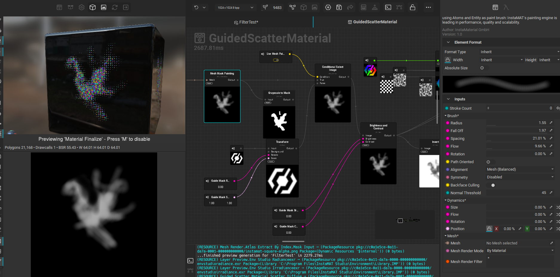
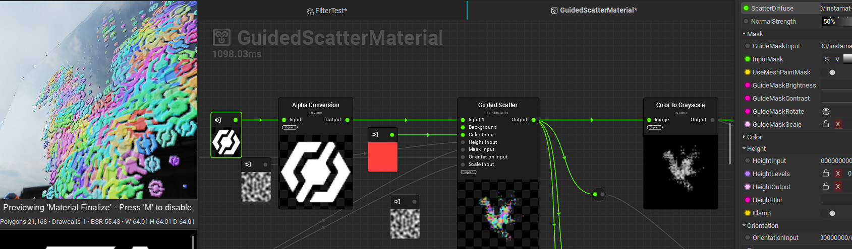
Being able to either pick an existing image / mask for the guided scatter OR being able to simply paint a mask with a brush and use that as the guided scatter input for where to scatter these pattern/decals.

I´m not sure its possible, but I know a lot more is possible with Instamat than you may initially think, due to its very granular procedural approach, so, we´ll see…

  1. I started out with the PBR template, since that would be the target output of my graph: A PBR material layer.
    In that graph, there was a “Material make” node, so I was assuming its something similar as the “make material attribute” node in Unreal, that simply ties together some inputs you create earlier in the graph and outputs it as a material.
  2. As I was going to scatter patterns/decals, I´d need an opacity output, as voidberg kindly showed me on discord already.
    That node doesn´t have an opacity mask input slot though.
  3. I looked up the “Material make” node in the node reference and it says something about “link category” mode, but couldn´t find more info on that.

So: Whats the “link category” mode and why should I use the “Material make” node for it? I assume you could also make a material without it, simply by setting the outputs of the graph?

  1. Tied in is another importan question:
    If I decide to change the “Maker material” node in my current graph, by adding a slot for opacity…how do I know if its now gonna mess up EVERY other graph instancing this? Is the change JUST persisting in the current graph?
    I know there is some graphs you cannot open by double clicking, that give you an error message (something about cooked library maybe, I forgot the exact message), that makes me assume these nodes are “protected” for that exact reason, but I´d still like to understand whats going on before I mess things up, when I CAN open a node like “Make material”…:slight_smile:

  2. Another very basic question:
    I started out with the “layering” workflow, before I wanted to dive into the Canvas, as that has a much steeper learning curve for me.
    But I don´t understand the basics of where I define what kind of graph I´m building and which one to use for which use case…:
    There are multi channel elements (aka procedural materials?), masks, filters, effects and generators…
    I assume you need to define the category somewhere in the output section of a new graph?
    But I also don´t quite understand the basics of the “hierarchy” in the layer stack…
    Which type affects which other types? Like: A mask effects predominantly the multi channel element/brush etc, the “top” of the stack.
    But then: Does a generator affect the mask only or the whole multi layer channel? What about filters?
    How do I add a mask to a mask?
    Sometimes I´ll just start dragging graphs from the library onto layers and I get an error message about incompatibility, that I then don´t understand:
    If I add a “filter” or effect directly from the layer stack, the presets are presorted, so this can´t happen, that is probably the better way to work then…

There is a general confusion around this for me that would be great to get cleared up, so I can fully grasp where I´m gonna put in my energy, based on what I need to achieve…

If all of these have been answered in a previous stream/tutorial, feel free to just link to that and I´ll try to catch up, like I said, I´m generally preferring to just read up on these infos, but I understand that it´ll take some time to document everything, giving the sheer amount of stuff available in instamat…

Ok, after playing some more with it, here are some more observations and questions.

Sorry if its a lot, but its just insane what you can do here and its tough to not get lost in the possibilities…:slight_smile:

Again, if you already cover most of these questions in an existing video, I´m happy to watch that, I just don´t have time to watch through all of them…
I just don´t wanna bang my head against a wall, while learning, if it turns out that what I set out to do is actually just not possible in the way I imagine it,
Instamat is pretty magic, but its not a magic wand you can just wave around…:slight_smile:

  1. Quick note: I wasn´t able to use the finished graph, even though I added all the necessary outputs. The error when trying to drag the graph into a layering projects didn´t give me a clear idea of what I did wrong though:

Thanks to discord, the problem was actually easily fixed:
I had to put in the correct category.

Without anything selected, the graph info to the right actually shows you not just the graphs name, but also the category:

image

I just randomly named the category “Material/Effects” because I didn´t think it was important and that didn´t work of course.
After correcting it to “MaterialS/Decals” it worked!

In the future it would be nice if we could put in our own categories, for now it probably makes sense, as these categories are probably also internally used to filter through the vast library (maybe thats what tells the “add filter” buttons for example what “filters” are available).

  1. One thing I couldn´t get to work:
    Using a painted layer mask in a layering project as guide mask.
    Even though I was able to expose a switch parameter to let the user pick between an existing mask image and mesh painting a mask, It didn´t pick up on the painted mask.
    However: As i was shown on Discord as well…It IS possible to do exactly that in the canvas itself!!

You can then even do crazier things, like add a contrast or invert node after the mesh paint node and then plug your painted mask into different inputs of the guided scatter node, like scale or height…Or even create different masks for each of these inputs!

I´m still not sure wether its possible to also do this by directly painting in the layering project.
Because right now I´d have to go back to the canvas, pick the mesh I use in the layering project and then paint on the mask there.
I wouldn´t be able to see the underlying layers for example and I guess I´d have to duplicate the graph, if I wanted to use it with a different mesh in another layering project…

The ideal outcome would be, if I could just drop the graph in as a new element graph, then add as many masks as are mapped in the graph (for the different inputs) and then I could simply pick a different mask for each input or use the same mask for all inputs…
So I could paint one mask for the guide image, one for the scaling, one for rotation, one for height etc…the possibilies would be amazing…
Just imagine filling an element layer with scales decals and then PAINTING their orientation and scale, LIVE in the viewport…

I really hope this is already possible, as it IS possible in the canvas.

  1. RIght now, using the “Guided Scatter” node, I still have to run through some extra nodes to also create normal maps/height etc for each scattered shape.
    Its nice to have the extra control over these, but sometimes I´d prefer to essentially just plug in a premade material or graph (for example for skin damage) and just add its outputs and plug them into the guided scatter node, but the guided scatter node only has ONE output pin, so I can´t drag off from that to also get the right normals…

But, you know what: I noticed way too late, that there was also the “Atlas Material Scatter” node.
…which essentially seems to do pretty much what I just described, as far as I could see.

So, the question is: Would it be better to just build on this node? Or is there some stuff I´m missing here, thats not possible with that graph?

  1. Could I even add multiple materials in the “atlas material scatter node”?
    I noticed the node input was called “Material1”, but I couldn´t see an option to add more materials.
    And as its a built in graph, I cannot open it to create my own variant…or could I somehow…?

  2. I have a similar issue with the “guided scatter node”: I don´t see an input option for “density”. And I´d like to be able to map the density as well.
    Because, for example, if I add a scale input, to fade out the scattered shapes/decals, I´d want the density to be higher in the areas the scale fades out, to get a more natural transition (using an invert node on the scale input for example)

  3. Maybe I also don´t get how the guided scattering works in general, as it seems more like “tiling in an orderly fashion of rows and colums” than actual random scattering. Its a bit difficult this way to get more overlapping scatters, unless I really crank up the scale or density:

image

There is also the “random scatter” node, which seems to do more of what I need, but that doesn´t have all the other options like input mask for guided scattering…

Could you maybe elaborate a bit more on that?

  1. Another question: Is it possible to scatter on the Z axis, so to speak? Aka, give each scattered shape an individual per shape height?
    I plugged in a random noise texture into the height input of the guided scatter node, but that acts as global displacement input, rather then just individually putting some of the scatterd shapes more in the front and some more in the back.

If I use a black and white shape, I can add some random color variation and if I then convert the output from the guided scatter node into a greyscale map, I get sort of that effect:

But of course that doesn´t work if the input shape already has color or if I don´t want the color/luminance variation on the
single shades…

So, would there be another way to achieve this, or is the guided scatter node simply not the right thing to use to begin with…?

I´m sure I get some more play time this weekend and can figure out more stuff on my own…:slight_smile:

A lot of feedback :slight_smile: Thanks for sharing it @insertmesh - I’ll make sure to go through each point once I have a bit of headroom. Things are getting pretty heated over here with the upcoming update!

No worries, I was too sick to work more with instamat anyways…

Hope antibiotics are now getting rid of that infection and I have some more brainpower to play with stuff again…:slight_smile:

Looking forward to the new release too!

2 Likes

Sorry to hear about that. Hope you feel better soon!

1 Like